English
▼
Press ESC to close
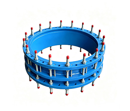
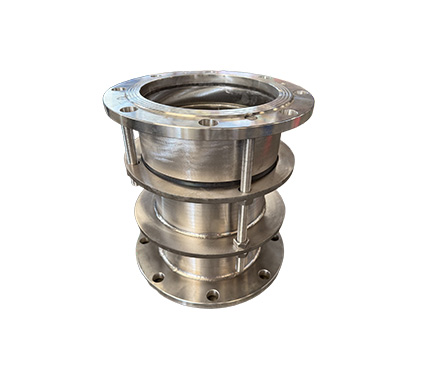
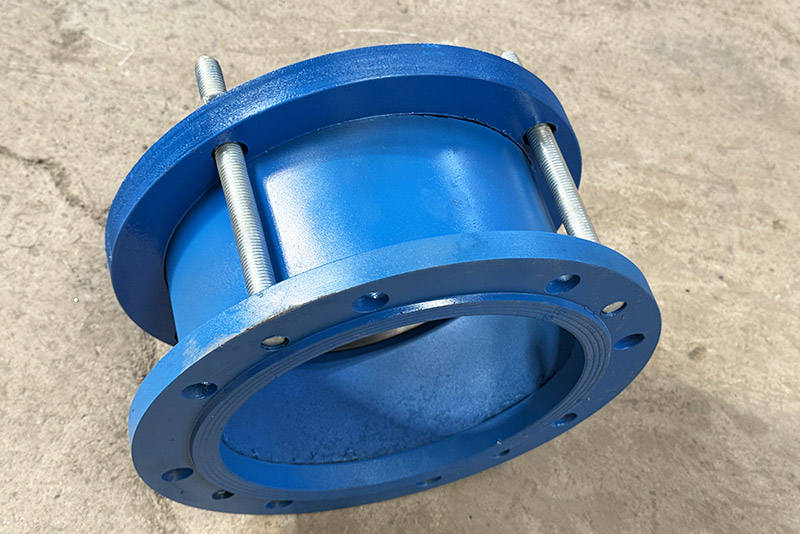
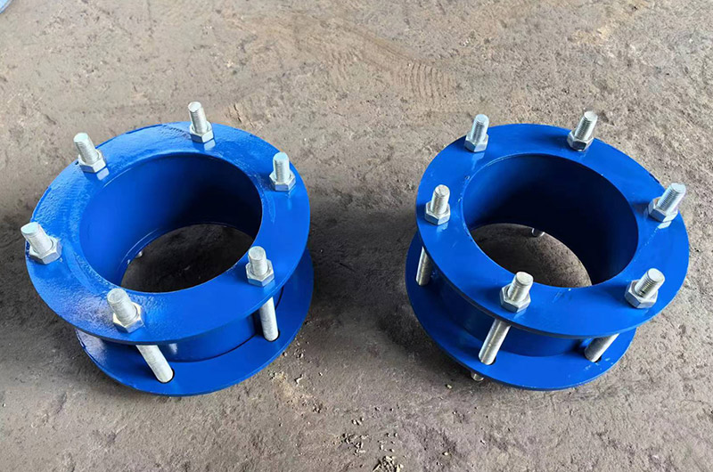
The compression-type expansion joint is a special axial compensation joint for marine pipelines. It is weld-free, corrosion-resistant, quick to install, and suitable for marine media such as seawater, oil, and fire fighting.
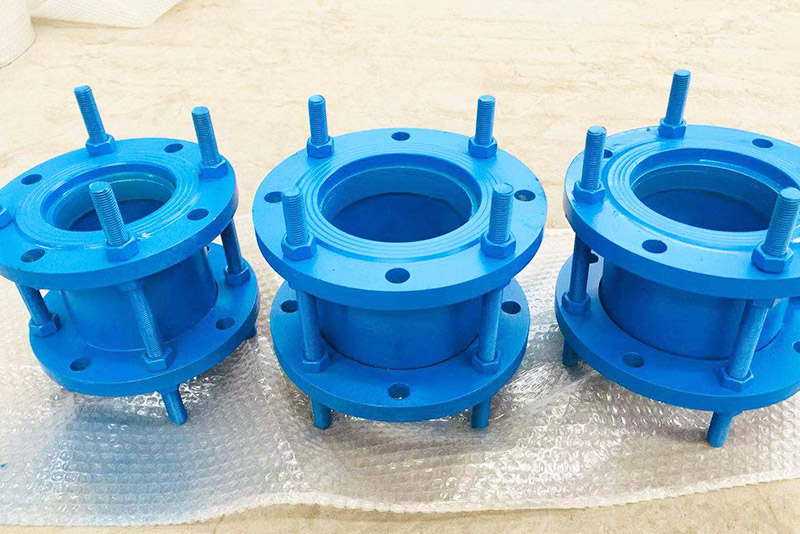
1. Axial Compensation: The inner pipe slides within the body, absorbing axial displacements caused by thermal expansion and contraction (±20–±50mm).
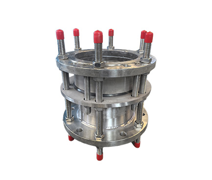
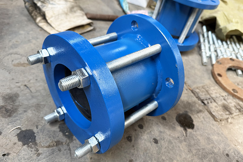
2. Gland Sealing: The bolts diagonally tighten the gland, pressing the sealing ring around the inner pipe, ensuring zero leakage of seawater or oil.
3. Welding-Free Quick Installation: Both ends are directly inserted into the pipeline without welding, suitable for confined spaces on ships.
Compatible with Marine Mediums: Seawater, freshwater, fire-fighting water, tank bottom sewage, fuel oil, lubricating oil, compressed air.
Low Pressure with Large Compensation: PN0.6/1.0MPa, sufficient compensation for hull deformation and vibration.
Lightweight Design: 40% lighter than double-flange versions, meeting ship weight reduction requirements.
Maintenence Under Pressure: Worn sealing rings can be directly pressed by the gland for maintenance without stopping ship operations.
1. Ship ballast water, seawater cooling, fire-fighting systems, tank bottom sewage, fuel/lubricating oil pipelines.
2. Deck washing, domestic freshwater, air conditioning circulating water pipelines.
3. Engine room/pump room pipelines with significant hull deformation or vibration.
4. Ship pipelines in confined spaces, requiring frequent maintenance.
1. Axial installation: Insert both ends of the pipeline fully, leaving adequate expansion gaps.
2. Gland bolts should be tightened diagonally and evenly, ensuring the sealing ring is firmly pressed, watertight, yet flexible.
3. Marine pipelines must be equipped with fixed brackets to withstand internal pressure thrust.
4. Twisting or radial eccentric loading is strictly prohibited; installation can be horizontal or vertical.

| serial number | name | quantity | Material |
| 1 | Ontology | 1 | QT400-15、Q235A、ZG230-450、20 |
| 2 | sealing ring | 2 | NBR、CR、FPM、NR |
| 3 | Gland | 1 | QT400-15、Q235A、ZG230-450、20 |
| 4 | nut | n | Q235A、20、1Cr18Ni9Ti |
| 5 | studs | n | Q235A、35、1Cr18Ni9Ti |
| Nominal diameter DN | Pipe outer diameter Dw | Overall dimensions | Flange connection size | ||||||
| 0.6MPa | 1.0MPa | ||||||||
| L | L1 | D | D1 | n-do | D | D1 | n-do | ||
| 65 | 76 | 105 | 118 | 160 | 130 | 4-Φ14 | 185 | 145 | 4-Φ18 |
| 80 | 89 | 190 | 150 | 4-Φ18 | 200 | 160 | 8-Φ18 | ||
| 100 | 108 | 123 | 210 | 170 | 4-Φ18 | 220 | 180 | 8-Φ18 | |
| 100 | 114 | 210 | 170 | 4-Φ18 | 220 | 180 | 8-Φ18 | ||
| 125 | 133 | 240 | 200 | 8-Φ18 | 250 | 210 | 8-Φ18 | ||
| 125 | 140 | 240 | 200 | 8-Φ18 | 250 | 210 | 8-Φ18 | ||
| 150 | 159 | 260 | 225 | 8-Φ18 | 285 | 240 | 8-Φ22 | ||
| 150 | 168 | 260 | 225 | 8-Φ18 | 285 | 240 | 8-Φ22 | ||
| 200 | 219 | 320 | 280 | 8-Φ18 | 340 | 295 | 8-Φ22 | ||
| 250 | 273 | 130 | 375 | 335 | 12-Φ18 | 395 | 350 | 12-Φ22 | |
| 300 | 325 | 130 | 160 | 440 | 395 | 12-Φ22 | 445 | 400 | 12-Φ22 |
| 350 | 355 | 490 | 445 | 12-Φ22 | 505 | 460 | 12-Φ22 | ||
| 350 | 377 | 490 | 445 | 12-Φ22 | 505 | 460 | 12-Φ22 | ||
| 400 | 406 | 540 | 495 | 16-Φ22 | 565 | 515 | 16-Φ22 | ||
| 400 | 426 | 540 | 495 | 16-Φ22 | 565 | 515 | 16-Φ22 | ||
| 450 | 457 | 595 | 550 | 16-Φ22 | 615 | 565 | 16-Φ26 | ||
| 450 | 480 | 595 | 550 | 16-Φ22 | 615 | 565 | 16-Φ26 | ||
| 500 | 508 | 645 | 600 | 20-Φ22 | 670 | 620 | 20-Φ26 | ||
| 500 | 530 | 645 | 600 | 20-Φ22 | 670 | 620 | 20-Φ26 | ||
| 600 | 610 | 755 | 705 | 20-Φ26 | 780 | 725 | 20-Φ30 | ||
| 600 | 630 | 755 | 705 | 20-Φ26 | 780 | 725 | 20-Φ30 | ||
| 700 | 720 | 860 | 810 | 24-Φ26 | 895 | 840 | 24-Φ30 | ||
| 800 | 820 | 220 | 225 | 975 | 920 | 24-Φ30 | 1015 | 950 | 24-Φ33 |
| 900 | 920 | 1075 | 1020 | 24-Φ30 | 1115 | 1015 | 28-Φ33 | ||
| 1000 | 1020 | 1175 | 1120 | 28-Φ30 | 1230 | 1160 | 28-Φ36 | ||
| 1200 | 1220 | 1405 | 1340 | 32-Φ36 | 1455 | 1380 | 32-Φ40 | ||
| 1400 | 1420 | 270 | 1630 | 1560 | 36-Φ42 | 1675 | 1590 | 36-Φ42 | |
| 1600 | 1620 | 1830 | 1760 | 40-Φ42 | 1915 | 1820 | 40-Φ48 | ||
| 1800 | 1820 | 2045 | 1970 | 44-Φ42 | 2115 | 2020 | 44-Φ48 | ||
| 2000 | 2020 | 2265 | 2180 | 48-Φ42 | 2350 | 2230 | 48-Φ48 | ||
| 2200 | 2220 | 275 | 2475 | 2390 | 52-Φ42 | 2550 | 2440 | 52-Φ56 | |
| 2400 | 2420 | 2685 | 2600 | 56-Φ42 | 2760 | 2650 | 60-Φ56 | ||
| 2600 | 2620 | 240 | 300 | 2905 | 2810 | 60-Φ48 | 2960 | 2850 | 60-Φ56 |
| 2800 | 2820 | 3115 | 3020 | 64-Φ48 | 3180 | 3070 | 64-Φ56 | ||
| 3000 | 3020 | 3315 | 3220 | 68-Φ48 | 3405 | 3290 | 68-Φ60 | ||
| Note: This dimension conforms to GB/T12465-2002 standard. | |||||||||
| Instructions: After installation on the pipeline, tighten the nut and elastic sealing ring. Under the action of the nut and gland, they are inclined towards each other and pressed tightly against the outer ring of the pipe, providing a seal and connection. When the temperature changes, the pipe can freely expand and contract in the middle of the joint. When the foundation settles, the pipe can deflect, ensuring a leak-free seal, thus achieving automatic compensation. Production range: DN32-400 | |||||||||