English
▼
Press ESC to close
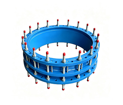
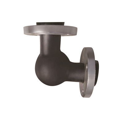
Double-flange limit expansion joints are axial compensation and safety protection accessories for pipeline systems. They are connected by flanges at both ends and have built-in limit bolts to prevent excessive expansion and contraction, pull-out, or damage to equipment.
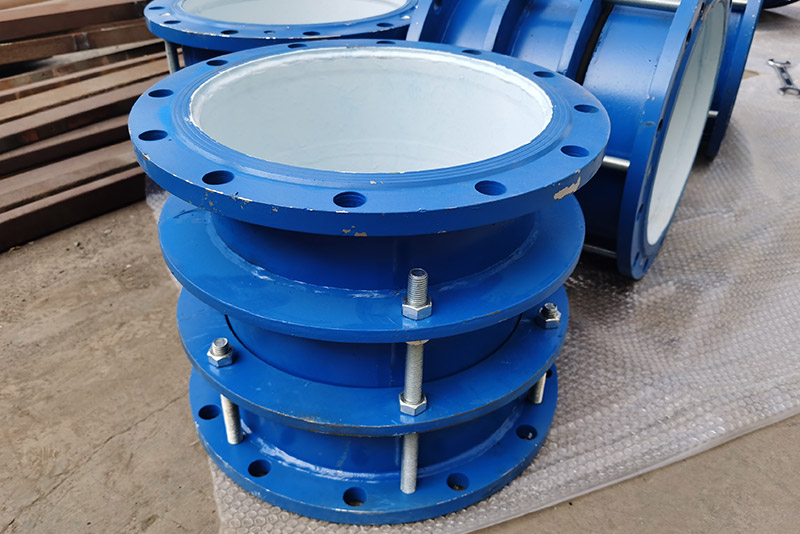
1. Main body: flanges at both ends, connected to the pipeline.
2. Telescopic tube: Can slide inside the main body to achieve axial compensation.
3. Sealing ring: rubber or graphite packing, dynamic sealing for leak prevention.
4. Gland: Presses the sealing element tightly, with adjustable preload force.
5 Limit screw double nut: controls maximum expansion and contraction; if excessive, it will lock.
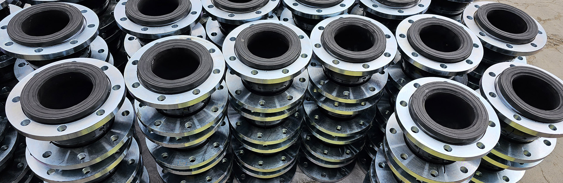
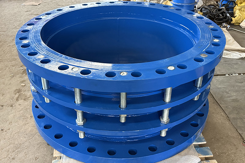
Bidirectional flange: Easy to install, stable connection.
Telescopic Limit: Can compensate for displacement and prevent overreach accidents.
Reliable sealing: dynamic sealing, suitable for hot and cold media.
Buffering and vibration reduction: absorbs vibration and water hammer impact, protecting the pipe network.
Diverse materials: carbon steel, stainless steel, ductile iron, suitable for different media and pressures.
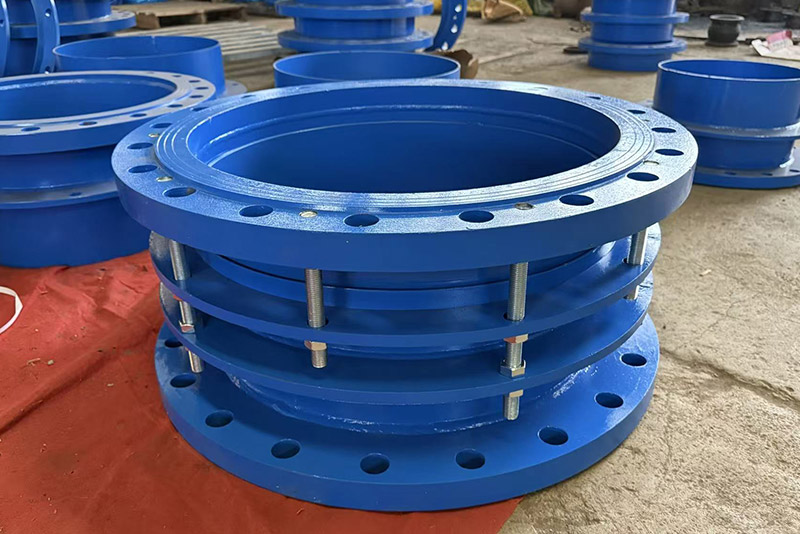
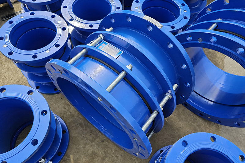
1. Expansion compensation: During thermal expansion, contraction, or settlement, the expansion tube slides inside the body to absorb axial displacement (commonly 50–300mm).
2. Dynamic sealing: The sealing ring slides with the telescopic tube, always adhering to the tube wall; the higher the pressure, the tighter the seal.
3. Limit protection: bolts loosen during normal expansion and retraction; When the preset limit is reached, the double nuts seize the flange, preventing further displacement and protecting pumps, valves, and other equipment.
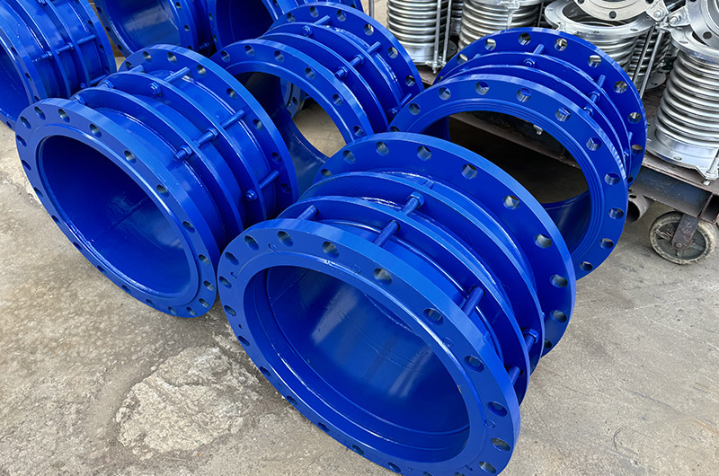
1. Municipal water supply and drainage: long-distance straight pipe sections to compensate for thermal expansion and contraction.
2. Heating/Heating: Compensation for axial displacement of hot water pipelines.
3 Pump room/pump station: pump inlet and outlet, vibration damping, convenient maintenance.
4. Buildings and settlement joints: absorb uneven settlement displacement of the foundation.
5. Chemical/Industrial Pipelines: Conveying hot and cold media, buffering vibrations and pressure fluctuations.
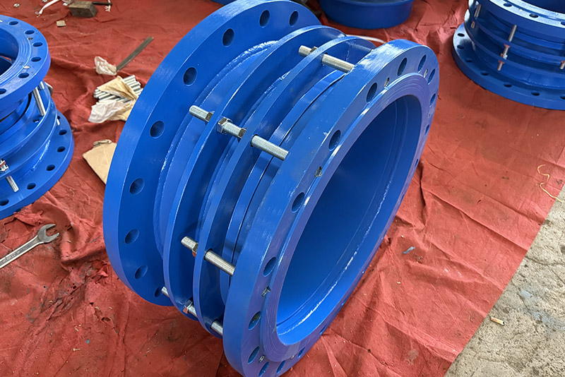
1. Both end flanges are coaxial with the pipeline to avoid uneven loading.
2. Evenly tighten the gland bolts diagonally, ensuring moderate sealing and flexible expansion and contraction.
3. Preset the limit nut to the design expansion limit, leaving a gap during normal operation.
4. Fixed brackets cannot be replaced; thrust supports must be separately installed at the pump outlet.

| serial number | name | quantity | Material |
| 1 | Ontology | 1 | QT400-15、Q235A、ZG230-450、20 |
| 2 | sealing ring | 1 | NBR |
| 3 | Gland | 1 | QT400-15、Q235A、ZG230-450、20 |
| 4 | Limiting short pipe | 1 | Q235A、20、16Mn |
| 5 | long stud | n | Q235A、35、1Cr18Ni9Ti |
| 6 | nut | 4n | Q235A、20、1Cr18Ni9Ti |
| 7 | studs | n | Q235A、35、1Cr18Ni9Ti |
| Nominal diameter DN | Pipe outer diameter Dw | Overall dimensions | Amount of expansion △L |
Flange connection size | ||||||
| 0.6MPa | 1.0MPa | |||||||||
| L | L1 | D | D1 | n-do | D | D1 | n-do | |||
| 65 | 76 | 340 | 105 | 50 | 160 | 130 | 4-Φ14 | 185 | 145 | 4-Φ18 |
| 80 | 89 | 190 | 150 | 4-Φ18 | 200 | 160 | 8-Φ18 | |||
| 100 | 108 | 210 | 170 | 220 | 180 | |||||
| 114 | ||||||||||
| 125 | 133 | 340 | 105 | 50 | 240 | 200 | 8-Φ18 | 250 | 210 | 8-Φ18 |
| 140 | ||||||||||
| 150 | 159 | 265 | 225 | 8-Φ18 | 285 | 240 | 8-Φ22 | |||
| 168 | ||||||||||
| 200 | 219 | 320 | 280 | 340 | 295 | |||||
| 250 | 273 | 375 | 335 | 12-Φ18 | 395 | 350 | 12-Φ22 | |||
| 300 | 325 | 350 | 130 | 65 | 440 | 395 | 12-Φ22 | 445 | 400 | |
| 350 | 377 | 490 | 445 | 505 | 460 | 16-Φ22 | ||||
| 400 | 426 | 540 | 495 | 16-Φ22 | 565 | 515 | 16-Φ26 | |||
| 450 | 480 | 595 | 550 | 615 | 565 | 20-Φ26 | ||||
| 500 | 530 | 645 | 600 | 20-Φ22 | 670 | 620 | ||||
| 600 | 630 | 755 | 705 | 20-Φ26 | 780 | 725 | 20-Φ30 | |||
| 700 | 720 | 860 | 810 | 24-Φ26 | 895 | 840 | 24-Φ30 | |||
| 800 | 820 | 590 | 220 | 130 | 975 | 920 | 24-Φ30 | 1015 | 950 | 24-Φ33 |
| 900 | 920 | 1075 | 1020 | 1115 | 1050 | 28-Φ33 | ||||
| 1000 | 1020 | 1175 | 1120 | 28-Φ30 | 1230 | 1160 | 28-Φ36 | |||
| 1200 | 1220 | 1405 | 1340 | 32-Φ33 | 1455 | 1380 | 32-Φ40 | |||
| 1400 | 1420 | 1630 | 1560 | 36-Φ36 | 1675 | 1590 | 36-Φ42 | |||
| 1500 | 1520 | 1730 | 1660 | |||||||
| 1600 | 1620 | 1830 | 1760 | 40-Φ36 | 1915 | 1820 | 40-Φ48 | |||
| 1800 | 1820 | 2045 | 1970 | 44-Φ40 | 2115 | 2020 | 44-Φ48 | |||
| 2000 | 2020 | 2265 | 2180 | 48-Φ42 | 2325 | 2230 | 48-Φ48 | |||
| 2200 | 2220 | 2475 | 2390 | 52-Φ42 | 2550 | 2440 | 52-Φ56 | |||
| 2400 | 2420 | 2685 | 2600 | 56-Φ42 | 2760 | 2650 | 56-Φ56 | |||
| 2600 | 2620 | 600 | 240 | 140 | 2905 | 2810 | 60-Φ48 | 2960 | 2850 | 60-Φ56 |
| 2800 | 2820 | 3115 | 3020 | 64-Φ48 | 3180 | 3070 | 64-Φ56 | |||
| 3000 | 3020 | 3315 | 3220 | 68-Φ48 | 3405 | 3290 | 68-Φ60 | |||
| Note: This dimension conforms to GB/T12465-2002 standard. | ||||||||||
| Instructions: This product is suitable for connections to flanges on both ends. During installation, adjust the length of the connections at both ends, tighten the gland bolts diagonally and evenly, and then adjust the limit nuts. This allows the pipeline to expand and contract freely, locking the amount of expansion and contraction to ensure safe pipeline operation. Production range: DN32-4000. | ||||||||||