English
▼
Press ESC to close
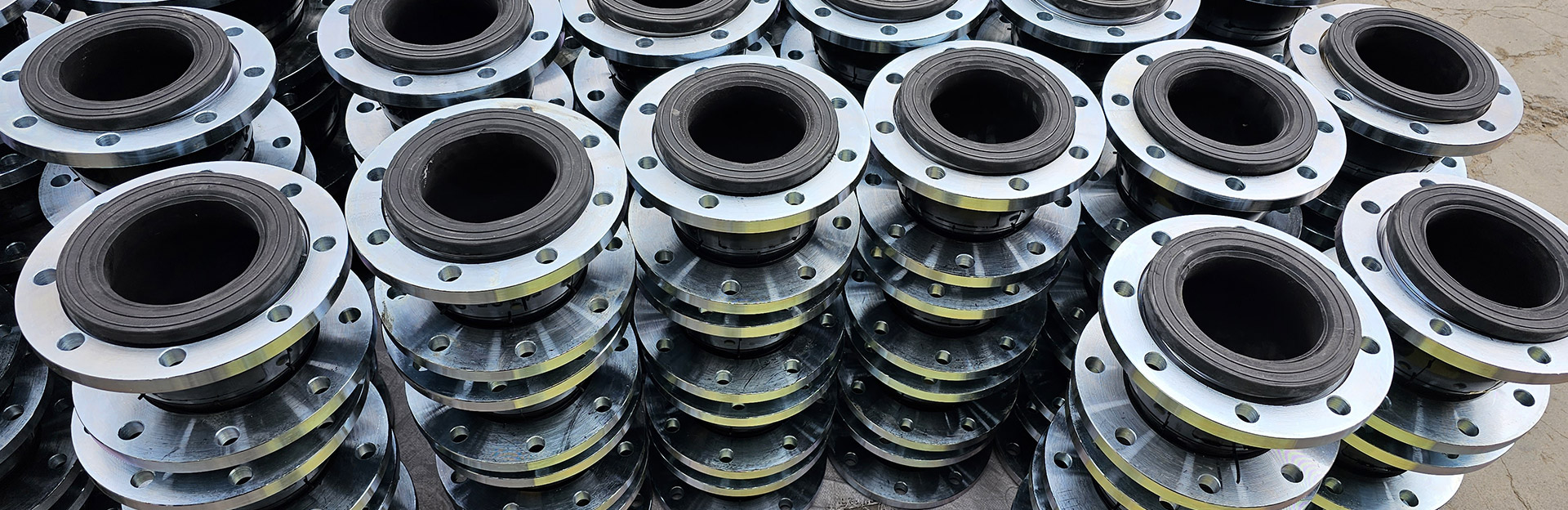
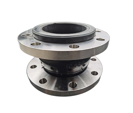
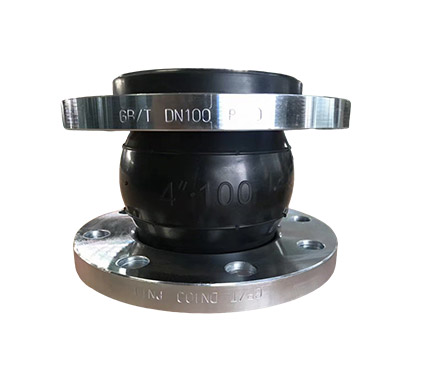
The concentric reducing rubber expansion joint, also called a reducing rubber expansion joint or a reducing rubber expansion joint, has two ends with different diameters, but their centers are on a straight line. It combines four functions: diameter reduction, vibration damping, noise reduction, and expansion compensation. It replaces traditional reducers with ordinary rubber joints, simplifying installation and reducing leakage points.
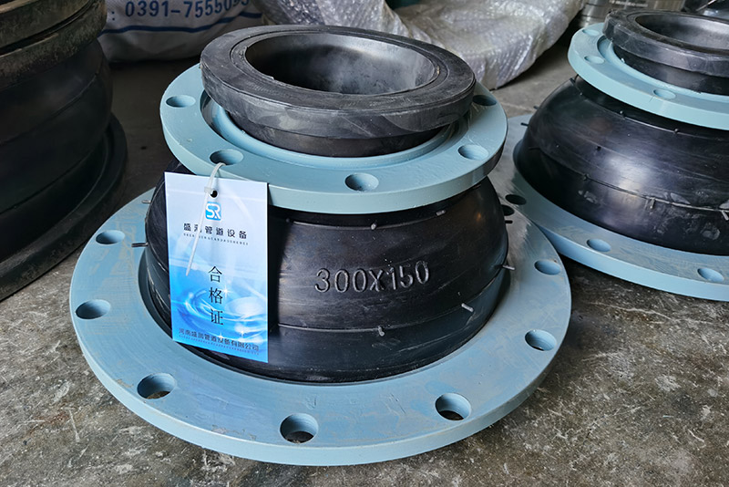
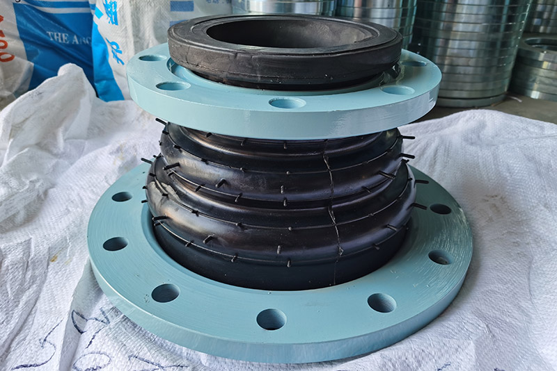
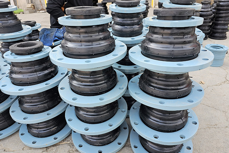
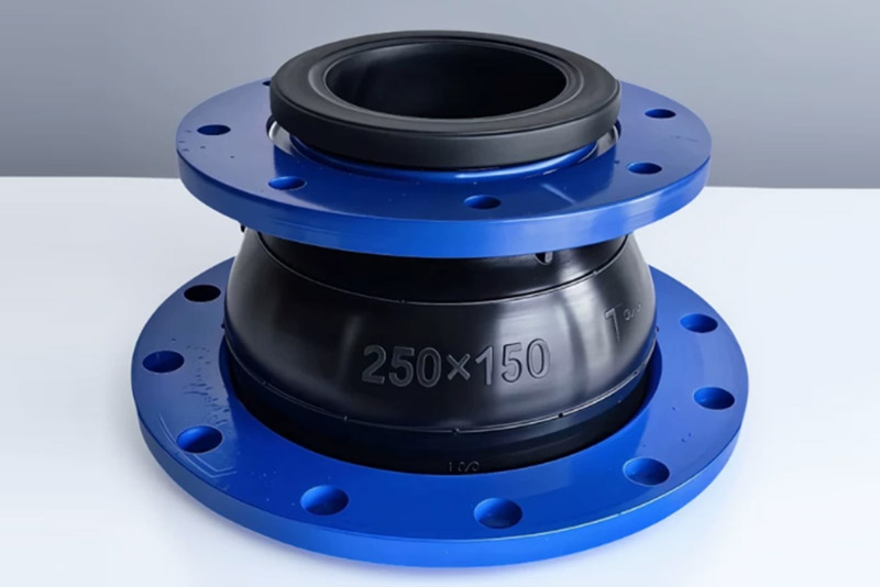
1. Rubber Sphere: One-piece vulcanized molding with a central tapered diameter reducing structure. Multiple layers of thickened fabric ensure pressure resistance and durability.
2. Carbon Steel Loose Flange: Can rotate freely, easy to install and align with screw holes.
3. Rubber Inner Layer: Water-resistant, corrosion-resistant, wear-resistant, and anti-aging.
4.Optional anti-pull-out limit screws to prevent high-pressure detachment.
Based on the elastic properties of rubber:
1. Changes the pipe diameter, achieving pipe size conversion.
2. Absorbs the expansion and contraction displacement caused by thermal expansion and contraction of the pipe.
3. Reduces pump vibration, preventing it from being transmitted throughout the entire pipeline.
4. Alleviates pipe installation misalignment and angular deviations.
1. One-piece molding, reducing joint gaps and minimizing leaks.
2. Excellent shock absorption and noise reduction, protecting pipes and valves.
3. Resistant to acids and alkalis, corrosion-resistant, suitable for various media.
4. Simple installation, shortening construction period.
5. Reduces pipeline pressure impact, extending equipment life.
1. Pump inlet and outlet diameter changes
2. Water supply, drainage, fire protection, and HVAC pipelines
3. Sewage treatment pipelines
4. Chemical equipment pipeline connections
5. Transition points for inconsistent pipe diameters

| Item\Model | KXD(DN50~300) | KXD(DN350~600) | Remark |
| Working pressure MPa | 1.0(10) | 0.6(6) | For media such as oil, acids, and alkalis, or those with special operating temperature requirements, we can also customize products by sending us a letter or drawing. Please specify this when ordering. |
| Explosion pressure (MPa) | <1.8 | <1.5 | |
| Vacuum degree Kpa | 86.7 | 53.3 | |
| Applicable temperature℃ | -20℃ to +115℃; special models can reach -30℃ to +250℃. | ||
| Applicable media | Air, compressed air, water, seawater, hot water, oil, acids and alkalis | ||
| Main features: It solves the problem of different diameters when connecting metal pipes, and also has vibration damping and noise reduction functions, saving on pipe installation parts and reducing costs. It consists of a rubber ball composed of an inner rubber layer, nylon cord reinforcement, and an outer rubber layer, and a loose-fitting metal flange. It features high pressure resistance, good elasticity, large displacement, ability to balance pipe deviation, vibration absorption, good noise reduction, and easy installation. It can be widely used in pipeline systems for water supply and drainage, circulating water, HVAC, fire protection, papermaking, pharmaceuticals, petrochemicals, shipbuilding, pumps, compressors, and fans. The standard type is used to transport media such as air, compressed air, water, seawater, oil, acids, and alkalis at temperatures ranging from 15℃ to 120℃. The special type is used to transport the above media or oil, concentrated acids and alkalis, and solid materials at temperatures ranging from -30℃ to above 250℃. | |||
| serial number | name | quantity | Material |
| 1 | Inner and outer glue | 1 set | NR、NBR、EPDM |
| 2 | Main skeleton | 1 set | Nylon curtain |
| 3 | booster ring | 1 set | wire rope |
| 4 | flange | 2 pieces | Q235 stainless steel |
| DN large × DN small | Length L mm |
Axial displacement (mm) | Lateral displacement mm |
deflection angle(α₁+α₂)° | Remark | |
| elongation | compression | |||||
| 80×50 | 180 | 20 | 30 | 45 | 35 | The connecting flanges are manufactured according to the relevant data in the "National General Water Supply and Drainage Standard Atlas S311". |
| 100×80 | 180 | 20 | 30 | 45 | 35 | |
| 150×80 | 200 | 20 | 30 | 45 | 35 | |
| 150×100 | 200 | 22 | 30 | 45 | 35 | |
| 200×100 | 200 | 22 | 30 | 45 | 35 | |
| 200×150 | 200 | 22 | 30 | 40 | 35 | |
| 250×200 | 220 | 25 | 35 | 40 | 30 | |
| 300×200 | 220 | 25 | 35 | 40 | 30 | |
| 300×250 | 220 | 25 | 35 | 40 | 30 | |
| 350×250 | 240 | 25 | 35 | 40 | 30 | |
| 350×300 | 240 | 25 | 38 | 35 | 30 | |
| 400×350 | 240 | 25 | 38 | 35 | 30 | |
| 500×400 | 240 | 28 | 38 | 35 | 26 | |
| 600×400 | 240 | 28 | 38 | 35 | 26 | |
| 600×500 | 240 | 28 | 38 | 35 | 26 | |
| Notes: 1. Special requirements can be customized upon request (e.g., by letter or drawing). Flanges should conform to the "National General Water Supply and Drainage Standard Drawings," and other parts should be inspected according to HG/T2289-92. 2. For suspended water supply systems using products with a diameter of DN200 or larger, the pipe must have fixed supports or brackets; otherwise, the product should be equipped with an anti-pull-out device. 3. When using rubber joints, the corresponding flanges should be valve flanges or flanges conforming to GB/T9115.1 (RF). |
||||||